Heat source
Total load, heat-source position, contact area and allowable component temperature.
DIRECT LIQUID COOLING
A straightforward cooling architecture that combines a thermally conductive plate with an embedded copper flow path.
Discuss your application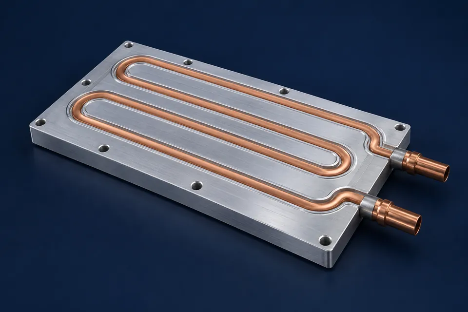
KEY FACTS
Total load, heat-source position, contact area and allowable component temperature.
Coolant, inlet temperature, flow rate, pressure and allowable pressure drop.
Plate dimensions, thickness, flatness, mounting holes and available clearance.
Tube size, inlet and outlet position, fittings and routing are confirmed for installation.
INDUSTRIES & APPLICATIONS
Tube-in-plate cold plates are suited to applications that need a mechanically simple liquid path and a plate shaped around the equipment interface.
Inverters, converters, IGBT modules and other high-power components.
Battery systems, charging equipment and power conditioning hardware.
Motor drives, lasers, controls and test equipment with continuous heat loads.
Processors, modules and assemblies where air cooling is insufficient or impractical.
TYPICAL USE CASES
Heat-source position, contact pressure and flatness requirements guide plate and mounting details.
Tube routing can be considered around multiple sources, mounting points and inlet/outlet constraints.
A dimensional drawing, clear photos or a sample reference can establish the starting geometry for review.
PRODUCT OVERVIEW
A tube-in-plate liquid cold plate conducts heat from mounted components into coolant flowing through an embedded copper tube. The plate spreads heat across its surface while the tube carries it to the wider cooling loop.
Tube location relative to the heat sources, bend radius, plate thickness and thermal contact between the tube and plate all influence performance. The external envelope must also accommodate fittings, mounting points and the required installation orientation.
For product matching, provide a drawing of the mounting surface and mark the heat-source areas where possible. Final construction, dimensions, ratings, testing scope and documentation are stated only in the corresponding quotation.
FAQ
Share the heat load, heat-source layout, coolant and temperatures, flow rate, pressure limits, plate envelope, mounting points, connections and quantity.
Yes. A drawing, marked-up photo, existing reference or dimensional sketch can help clarify the required interface.
No. Website images are product concept illustrations. Tube path, plate size, mounting and connections are confirmed for each quotation.
Include the preferred connection type, direction and available installation space so these details can be reviewed with the overall requirement.
CONTACT
Send the heat load, source layout, coolant conditions, plate envelope, connections and quantity.